


System Overview: Key Features
2-Unit (2) CubeSat Bus:
1U of internal payload volume
Nanoracks NRCSD compatible
1.5 W average bus consumption
Payload average power: 240 mW
Up to 5 W peak power
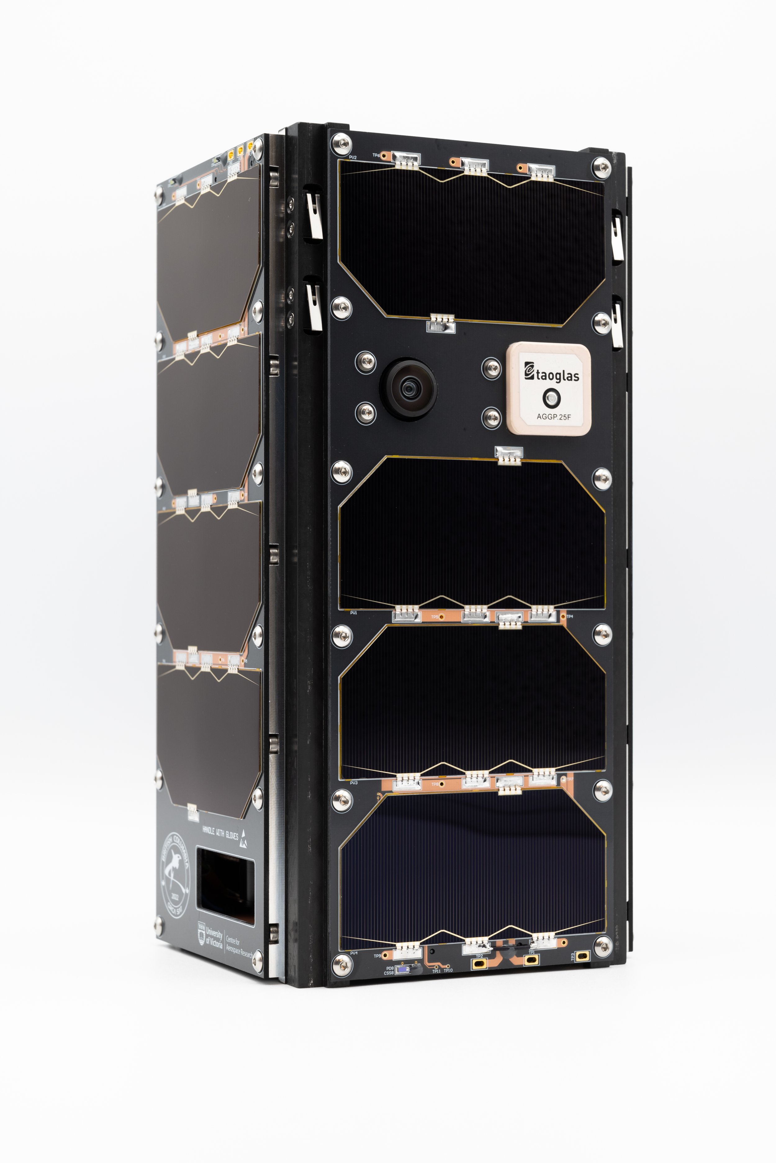
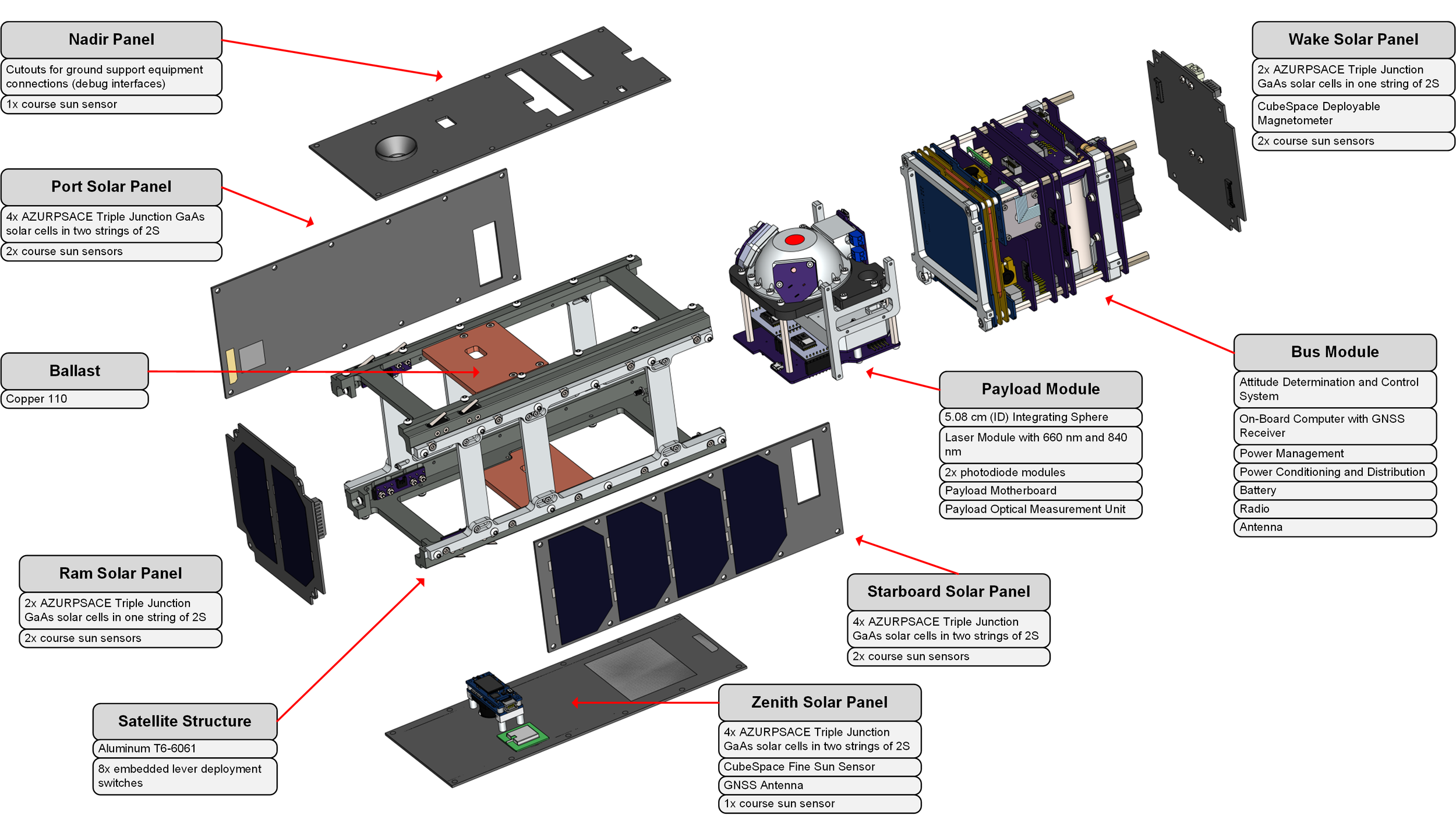
Solar array: Body-mounted panels
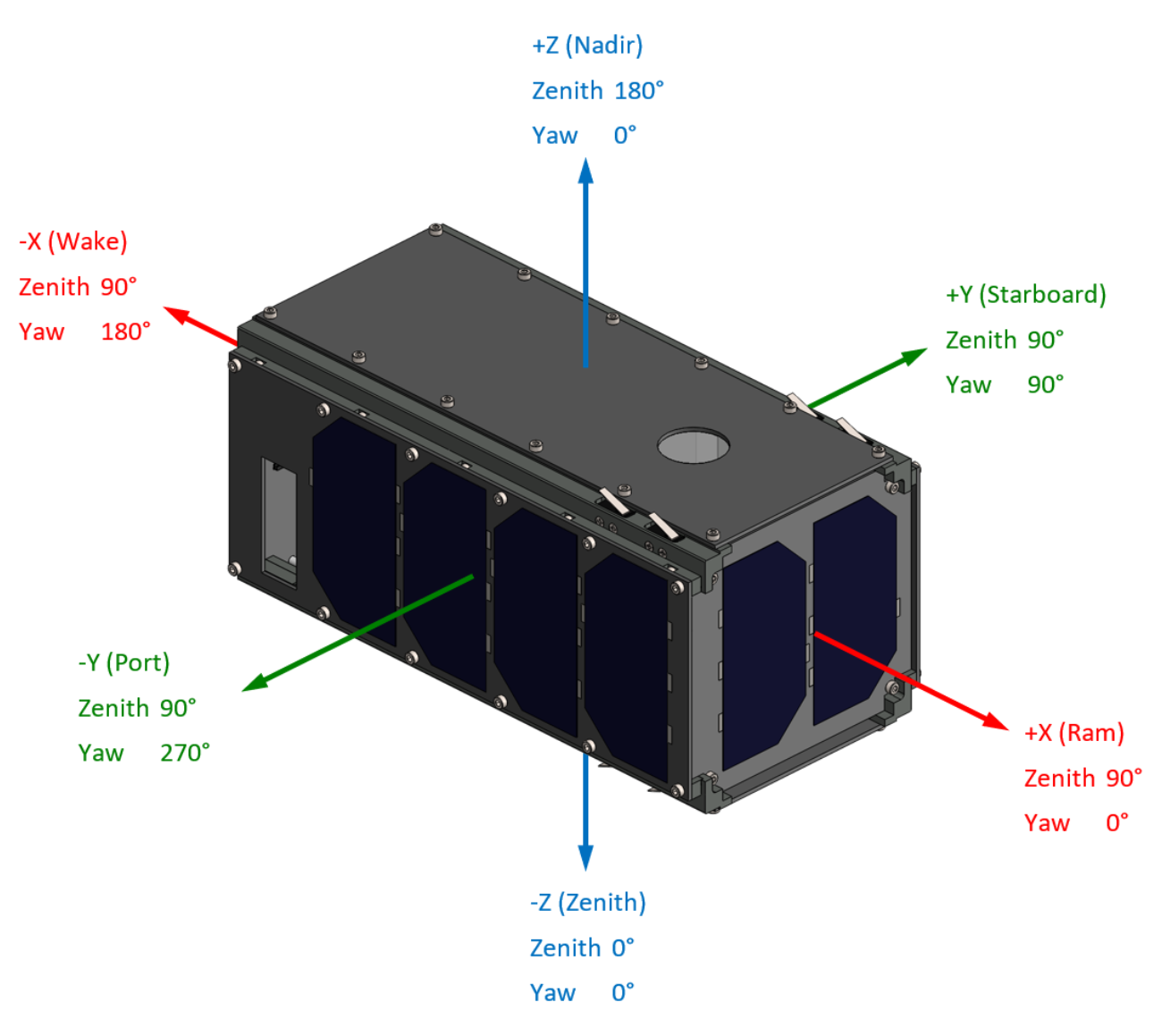
Solar panels on ±X, ±Y, and -Z faces.
7 W peak power.
Battery: 12 Whr LTO battery
Pointing accuracy:
Nadir pointing nominal
3-axis stabilization
1-axis (pitch) control
Roll and Yaw angles: < 5° error
Pitch angle control: < 1° error
On board GNSS receiver:
Time synchronization to UTC
Positioning, altitude, velocity data
Patch antenna on Zenith face
Data Rate: 10 kB/s down/uplink
Antenna: 437 MHz UHF dipole antenna
On Board Computer:
Safety-critical Arm Cortex-R5F
Dual-Core Lockstep CPU
Dual-redundant Real Time Clocks
Data storage: 128 Mb NOR Flash
Firmware storage: 128 Mb ECC NOR Flash
256 Kb MRAM
Over-the-air Firmware Updates
Housekeeping Telemetry Collection:
Temperature
Voltage, current, and power consumption
Logs and flags
Payload Data Bus: SPI
Propulsion: None
Expected mission life: 1.5 years in LEO
PC104 cards:
Accommodates off-the-shelf subsystems
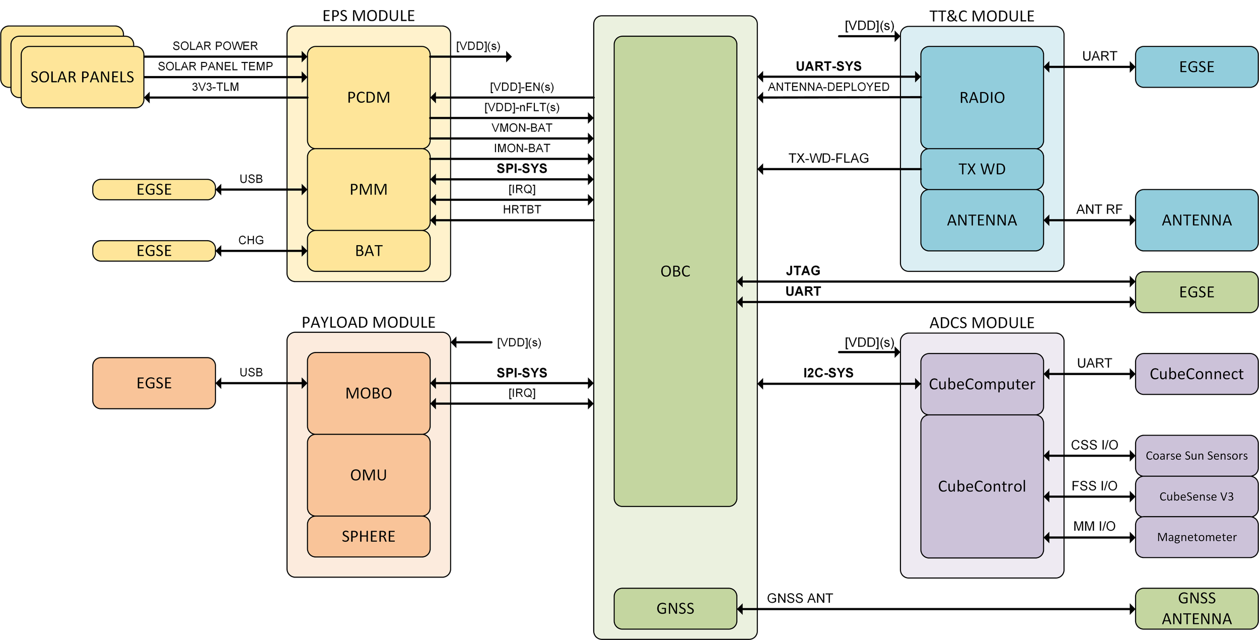
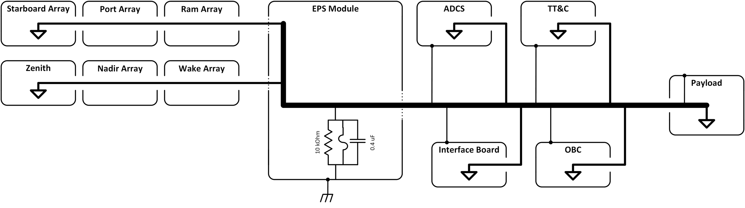
Satellite Bus Electronics


Satellite Structure


Satellite Structure Specifications
6061-T6 aluminum
Hard anodized rails
316 stainless steel fasteners
Loctite Blue 242 on all fasteners
Internal fasteners epoxied with 3M Scotch-Weld 2216 B/A Grey
Manufactured in Victoria BC
Accommodates PC104 cards
8x deployment levers
Omron D2F
Each pair wired in parallel for redundancy
Telemetry, Tracking, and Command


Transceiver Specifications
Overview
Inspired by and based on OpenLST by Planet
PC104 compliant form factor
Single 5V DC input with application specific low noise 3.3V and 4.2V rails
Input reverse polarity protection
Transmit power consumption of 5.12 W and receive power consumption 0.24 W
ESD protected digital & RF I/O
External watchdog for SoC and manual reset functionality
UART interfaces for C&DH & debug @ 9600bps
Bootloader programming via CC-DEBUGGER
Communication Parameters
ITU emission designator 25K0F1DBN
25 kHz necessary bandwidth
Uncoded 2-FSK modulation
Data whitening with the PN9 sequence
Custom packet radio format with variable packet length
Data rate of 10.17 kbit/s and deviation of 6.18 kHz
AES-128 uplink encryption (permitted by ITU RR. Vol. 1 ART. 25 Sect. I 25.1 § 1), and unencrypted downlink
Over the air firmware update capability
RF Parameters
Texas Instrucments CC1110 SoC
Qorvo RFFM6406 front end (PA & LNA)
SMA-F type RF output matched to 50 Ohm
Nominal TX power of 32 dBm at antenna port
Sensitivity of -112 dBm at 10.17 kbit/s data rate & 6.18 kHz deviation, using 2-FSK
On chip frequency offset (Doppler) compensation
TCXO frequency reference, 1.85 ppm accuracy
Receive SAW-type bandpass filter
DC blocked RF output
Regulatory & Testing Considerations
Hardware timer to comply with ITU RR. Vol. I ART. 22 Section I 22.1 (positive space station transmitter control, ISED approved method)
Experimentally verified compliance with out of band emission limits set out in ITU-R SM.1541-6
Experimentally verified compliance with spurious emission limits outlined in ITU-R SM.329-12 and Appendix 3 of the ITU Radio Regulations
Experimentally verified receiver sensitivity performance
Experimentally verified thermal performance in vacuum


Antenna Specifications
Overview
Half wavelength deployable tape dipole
Burn wire antenna deployment mechanism with GPIO interface to C&DH
Manual arming mechanism for deployment system for safe handling
PC104 compliant form factor with reduced header size to simplify assembly
Delrin antenna deployer, held shut but braided Dyneema fishing line
Construction
RG-178B/U coaxial feed with direct connection from the coaxial conductors to the dipole arms (no impedance matching network)
Lossy choke balun comprised of a single coax turn on a Fair-Rite Mix 61 round core (Fair-Rite P/N 2661480002)
Series bleed resistors (2x 10k 0603) on antenna arm connected to coax center conductor
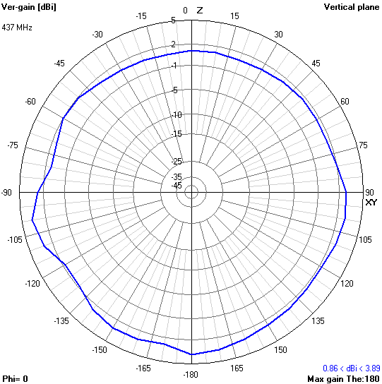
RF Characteristics
Tuned by length trimming after installation in spacecraft bus, measured input VSWR 1.02:1 at 437 MHz
Roughly 95% antenna efficiency, computer from anechoic chamber measurements
Peak gain of 3.89 dBi
Deployment from port-starboard sides of spacecraft, dipole pattern largely preserved
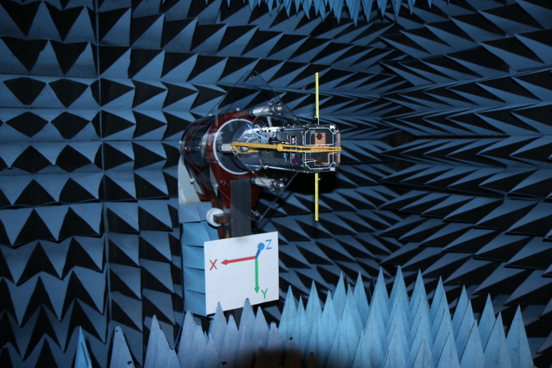
Testing
Initial in-house verification at University of Victoria anechoic chamber (directivity pattern, estimated max. gain, input characteristics) with tin spacecraft mock-up
In-depth characterization by Antenna Test Lab in their professional chamber with incomplete but realistic spacecraft model (ideal length estimate by manual tuning, input characteristics, gain pattern, efficiency at ideal length)
Final verification in flight-like spacecraft model at CSA David Florida Laboratory ATF2 facility


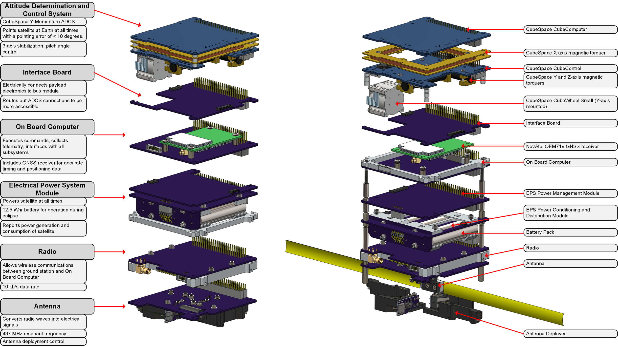
Attitude Determination and Control


Attitude Determination and Control System Specifications
Off-the-Shelf CubeSpace Y-Momentum ADCS
Sensors:
Deployable magnetometer
Fine sun sensor
Actuators:
2x Rod magnetorquers (±0.24 Am²)
1x Air core magnetorquer (±0.13 Am²)
Momentum wheel for momentum bias and pitch control
Speed range: ±8000 RPM
Max momentum: 1.77 mNms
Max torque: 0.23 mNm
Estimation Modes:
MEMS Rate Filter
Magnetic Rate Filter
TRIAD
Full-state EKF
MEMS Gyro EKF
Control Modes:
Detumbling
Y-Thomson
Nadir Pointing
Pointing Accuracy (Nadir Pointing Mode):
<10° in eclipse
<5° in sunlight
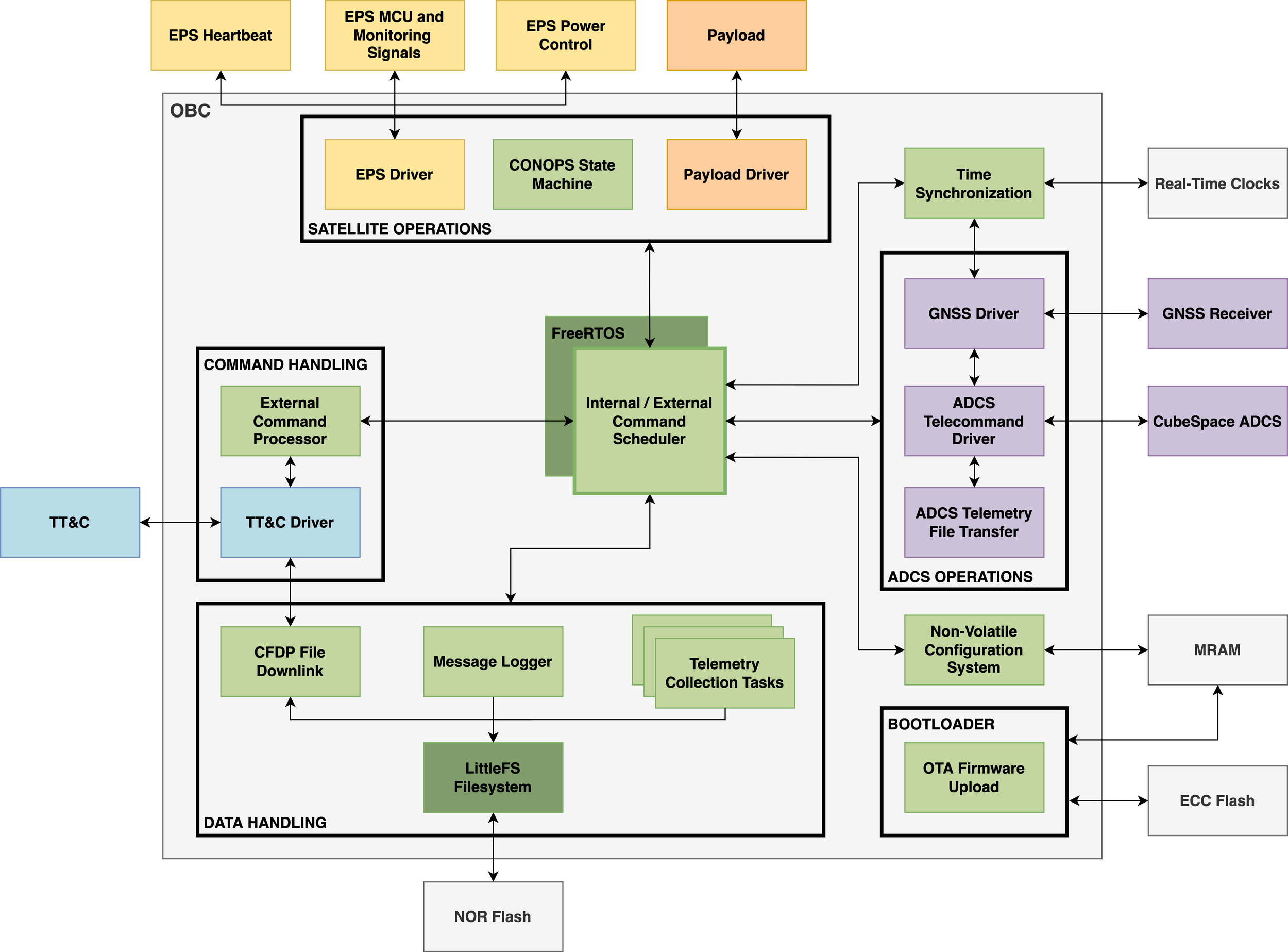
Command and Data Handling


On Board Computer Specifications
Processor:
Automotive-grade Texas Instruments TMS570 microcontroller
Dual ARM Cortex-R4F cores, operating in lock-step
ECC integrated flash and RAM banks
Radiation-tested up to 6 krad
Core clock: 80 MHz
External Memory:
Telemetry and Log File Storage: 128 Mb NOR flash
Firmware Storage: 128 Mb ECC NOR flash
Non-volatile Configuration Storage: 256 Kb MRAM
Auxiliary Components:
Dual-redundant real-time clocks
Hardware window watchdog
Temperature sensor
Integrated GNSS Receiver:
NovAtel OEM719
Operating System: FreeRTOS v9
Filesystem: ARM Mbed LittleFS
Files are organized in daily directories
One telemetry file exists per subsystem per day
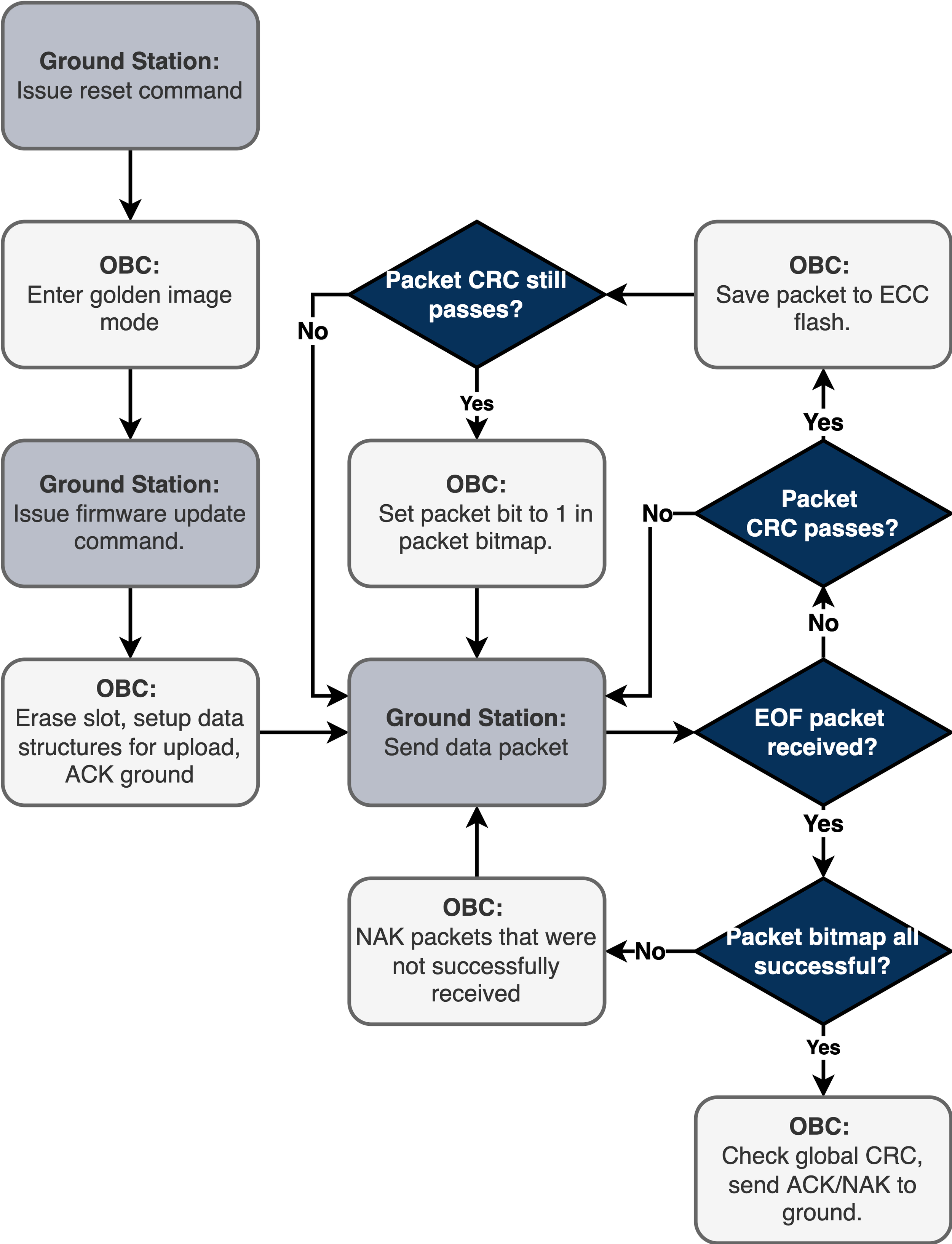
File Uplink and Downlink Protocol:
CCSDS File Delivery Protocol
Operated in deferred NAK mode
Command System:
Both immediate and scheduled commands are supported
One command is sent at a time; a single response is then awaited. A retry protocol is enacted if the response is not received within a certain timeout.
Non-volatile configuration table:
Table of non-volatile settings that allows tweaking of various configuration settings (eg. timeouts, counters) without requiring a new firmware upload
Each table is associated with a firmware version
Up to 3 tables are stored in MRAM
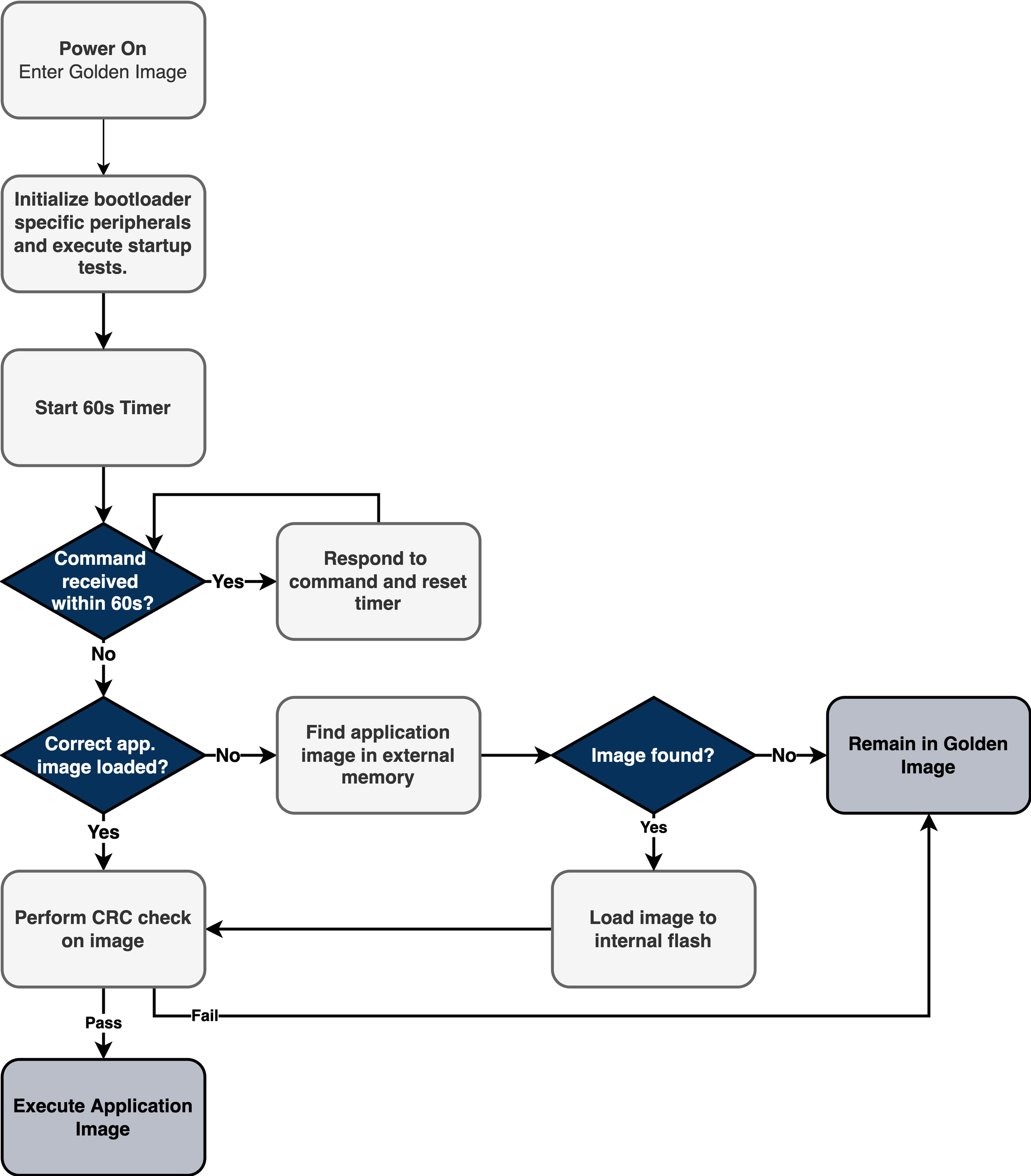
Bootloader:
Enables over-the-air firmware updates via CFDP protocol
One un-upgradeable image lives on-board at all times
Up to three slots available for uploading a new firmware image
Ground Control Software: Houston Application
Mission Control:
Custom Python GUI application
Built using Kivy 1.11
Automated ground pass set-up and execution
Manual command control and response display
File uplink and downlink interface
Log and data file viewing
Developed in parallel with OBC
Main tool for testing during development
Now doubles as ground control software for flight
Regression Testing:
Automated test sequencing and execution
PyTest framework
Command and response checking
Tests for bootloader and firmware uploads
Tests targeted at specific OBC firmware features and corner cases
Tests for integration of several subsystems
Tests for execution of the satellite concept of operations
Increment time on OBC
Check scheduled commands execute in correct order at correct time.
Firmware Unit Testing:
Telemetry Database
Database: MongoDB
Cloud Provider: fly.io
Frontend: NASA OpenMCT
Interfaces:
Control/testing over EGSE UART link
Control/testing over RF link with radio in-the-loop
Both wired and wireless links
Fun Statistics
Over the course of 4+ years, the on-board computer firmware repository has accumulated:
2546 commits
>32000 lines of code developed in-house
329 merge requests
Electrical Power System


Power Supply Unit Specifications
Maximum Power Point Tracking System:
All solar arrays connecting in parallel through blocking diodes
Tracks entire array
Defaults to fixed voltage tracking
Voltage sweep tracking on command
Efficiency:
High end-to-end efficiency
Day Time Efficiency: 83% average
Night Time Efficiency: 73% average
Multi-channel output:
Centralized converters
4x 3.3 V channels
2x 5 V channels
2x 12 V channels
1x unregulated channel
Output Power: 20 W across all channels
Power Conditioning and Distribution:
Voltage Accuracy: ±3%
Line Regulation: ±0.5%
Load Regulation: ±3.5%
Transient Recovery Time: 150 us
Transient Response: < 10% output voltage change, 0% to 100% load
Rise Time: < 10 ms
Ripple and Noise: < 2% Vp-p max, < 0.5% Vp-p average
Output Channel Protection:
Short Circuit Protection: Latch Off, < 5 us
Over Current Protection: Current limit, < 5 us response
Over Voltage Protection: Clamp at < 120% typical output voltage, < 10 us response
Fault flags to indicated if a channel has been shut down
Telemetry collection:
Current, charge (mA), and energy (mW) consumed per output channel
Battery SoC, Time at Full Charge, charge/discharge current, voltage, temperature
Solar array output voltage, current, and temperature
Power Management Interface: SPI
Debug Interface: USB
Turn On Condition:
In sunlight
Deployment switches released
Does not require charged battery to turn on
Launch Provider Compatibility:
Nanoracks NRCSD for space station deployment approved
Deployment Timer:
35 minute deployment timer
Heartbeat:
Requires 1 pps heartbeat from On Board Computer to keep alive
Resets all output channels for 11 seconds if heartbeat signal is interrupted.
Power Management Configurations:
Disables:
Entire power system (OFF EPS)
Just output channels (OFF DIST)
Enables:
Force on EPS (ON EPS)
Force on debug interface (ON TLM)
Timers:
Disable deployment timer (FAST ON)
Disable reset timer (OFF HEART)


Battery Pack Specifications
Total Energy:
12.2 Whr, 2.6 A @ 4.7 V average
Charge specifications:
CC/CV charge: 2.6 A (1C), 4 A (1.5 C) max, 5.3 V cutoff.
Discharge specifications:
8 A (3C) max discharge current, 3.2 V cutoff
Self Discharge:
< 1 % of capacity per week
Cell Type:
Hard cylindrical 65.4 mm x 18.5 mm
Lithium Titanate Oxide (LTO)
Operating Temperature:
Charge: -20 °C to 50 °C
Discharge: -35 °C to 75 °C
Thermal Control System:
Passive thermal control
Battery chemistry can safely charge/discharge at temperatures < -20 °C with no permanent capacity degradation
Configuration:
4 cells in 2S2P
No active balancing
Battery Management System:
Short Circuit Protection (21 A. 250 us response)
Over/Under Voltage Protection (5.46 V / 3.14 V, 1.25 s / 144 ms response)
Over Charge/Discharge Current Protection (9.1 A / 9.1 A, 8 ms response)
Latch off fault response
Voltage, current, and temperature monitoring
Nanoracks Compliant:
Passes Nanoracks NR-SRD-139 “Nanoracks Test Requirements for Lithium-ion Batteries Applicable to CubeSats & Small Satellites on the ISS”:
Cell and pack characterization/testing
Vacuum tested
Vibration tested (hybrid satellite/battery vibration test profile)


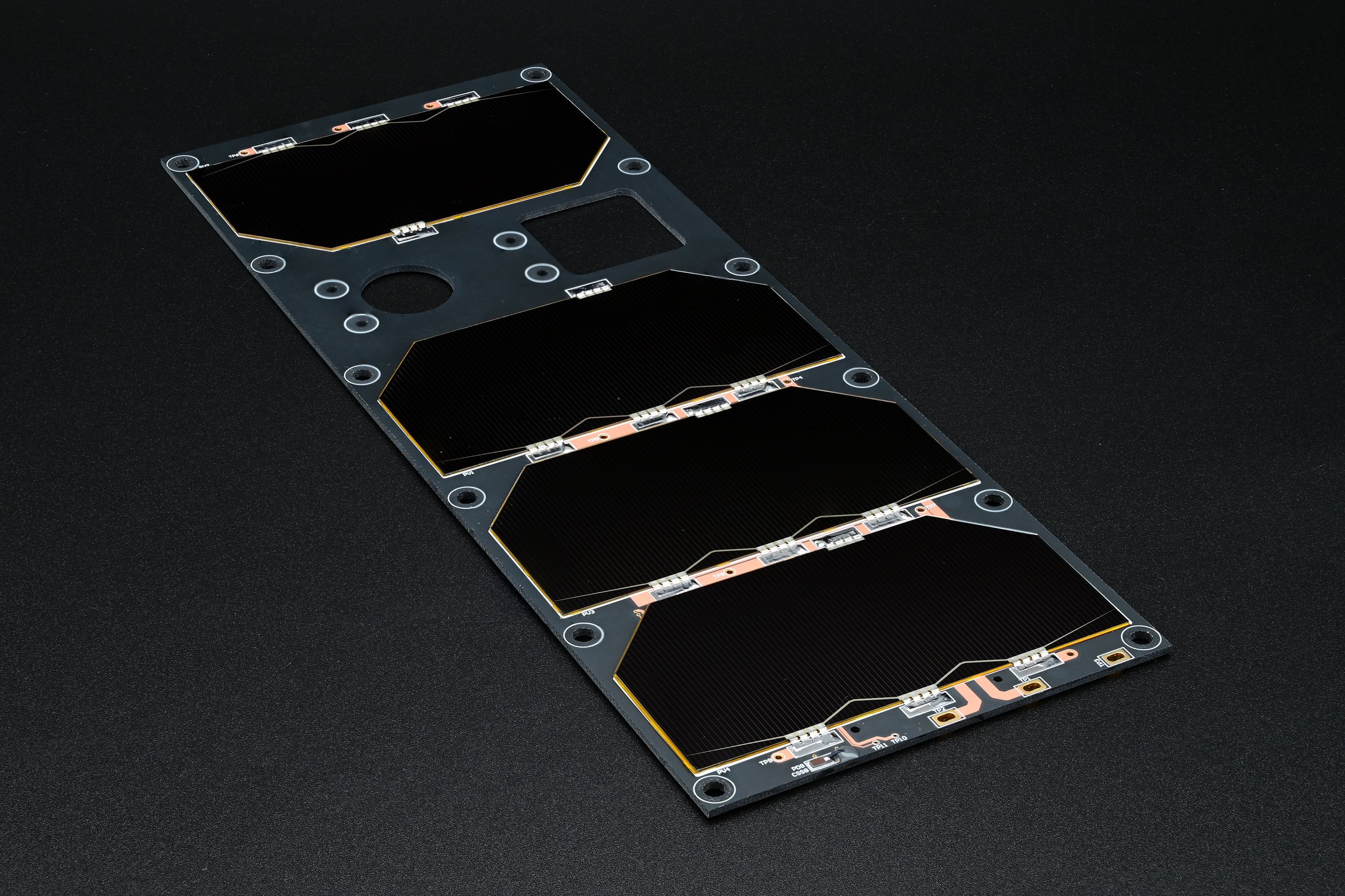
Power Generation:
Large panels (starboard, port, and zenith) produce 4.8 W peak
Small panels (ram and wake) produce 2.4 W peak
Solar Cell Type:
Azurspace Triple Junction GaAs solar cell assemblies
Integrated Sensors:
Course sun sensors for attitude estimation
Temperature sensors for thermal model validation
Substrate:
Ventec VT 447 b high absorptivity substrate
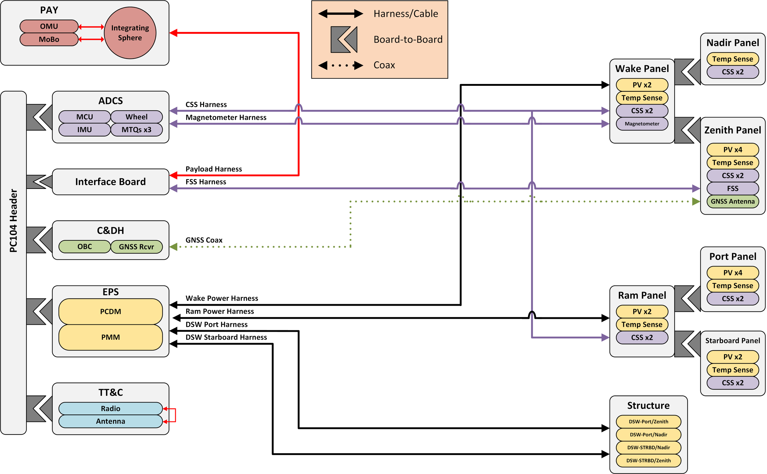
Connectors:
Large panels connect to ram/wake panels via board-to-board connectors (Samtec SIR1)
Small panels connect to EPS via cable harness (Molex Picolock)
Separate harness for course sun sensors to all direction connection to ADCS
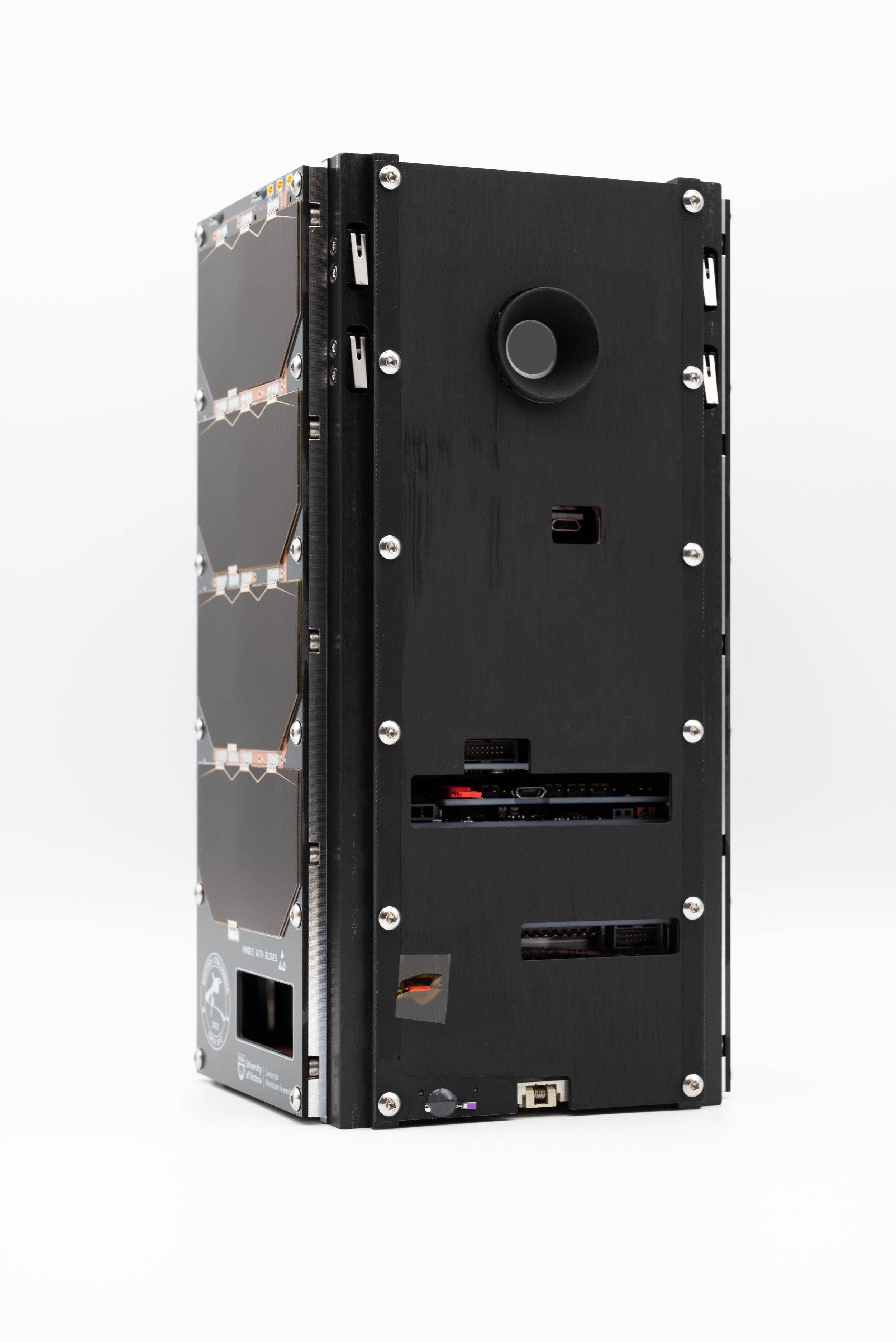
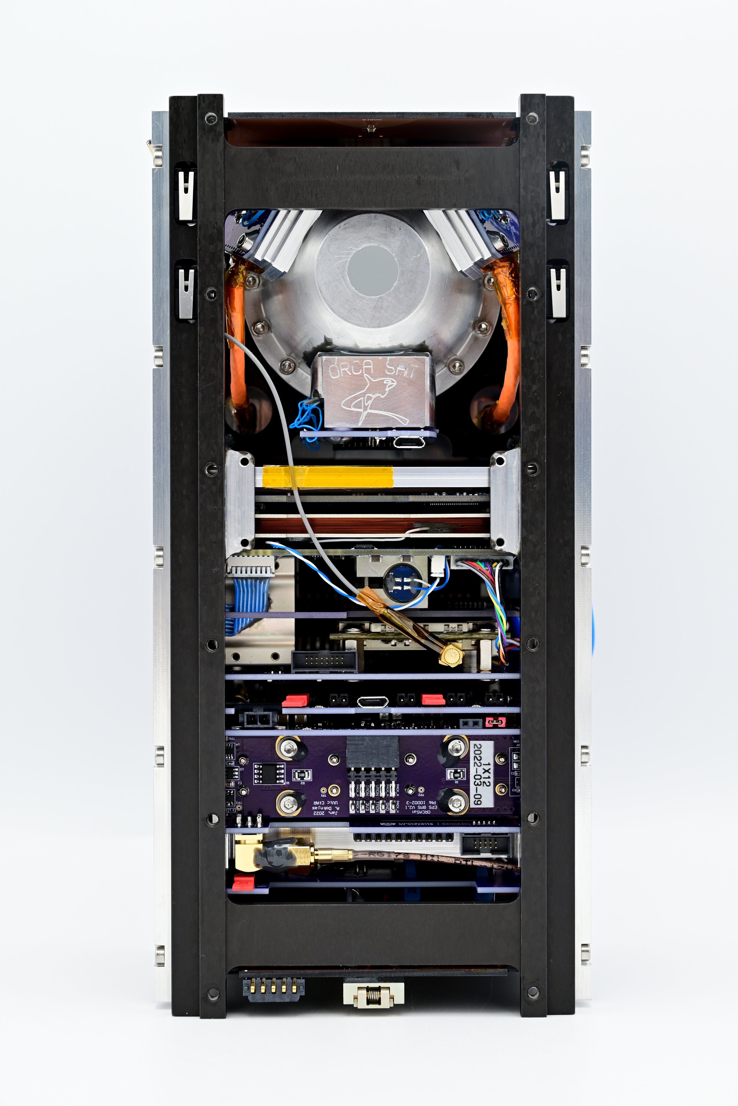
Satellite Bus Details
[1] Bus Module Bracket
[2] M2.5 Mounting Holes
[3] CubeSpace CubeComputer
[4] CubeSpace X-Axis Magnetic Torquer (air core)
[5] CubeSpace CubeControl
[6] CubeSpace Y-Axis Magnetic Torquer
[7] CubeSpace Z-Axis Magnetic Torquer
[8] CubeSpace CubeWheel Small (Y-Axis)
[9] Interface Board
[10] NovAtel OEM719 GNSS Receiver
[11] On Board Computer
[12] Power Management Module
[13] Power Conditioning and Distribution Module
[14] Battery Pack
[15] Radio
[16] Radio Heatsink/Shield
[17] Antenna PCBA
[18] Antenna Burn Wire Resistors
[19] Antenna Deployer
[20] Antenna Balun
(A) Fine Sun Sensor Connector
(B) Deployment Switch Connector (Starboard)
(C) Ram Solar Panel Connector
(D) Wake Solar Panel Connector
(E) Antenna Deployer Connector
(F) Magnetometer Connector
(G) OBC Debug Connector
(H) GNSS Antenna Connector
(I) EPS Ground Charge Connector (not shown)
(J) EPS Debug Connector (not shown)
(K) Battery Management System
(L) Battery Pack Connector
(M) Radio Antenna Connector
(N) Radio Configuration Access
(O) Radio Debug Connector
(P) Course Sun Sensor Connector
(Q) Payload Module Connector
(R) Deployment Switch Connector (Port)
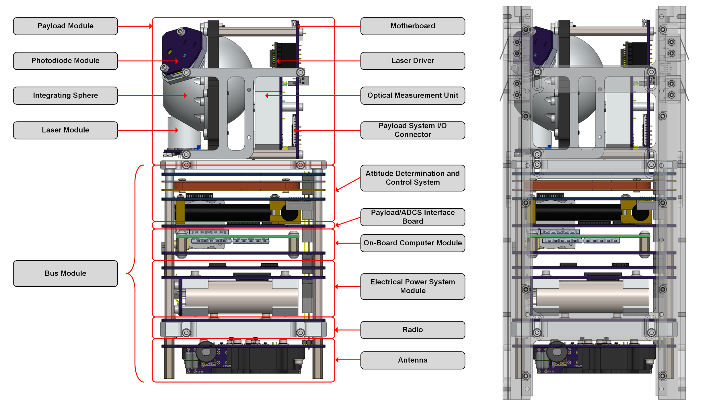
Exploded Views and Renders
Block Diagrams