"TinSat" and Antenna Testing
Author: Levente Buzas
One critical component of any TT&C subsystem is the radio antenna. ORCASat is no exception, we use a deployable half wavelength dipole, which we designed for the UHF amateur satellite allocation, between 435-438 MHz. Dipole antennas are conceptually simple -the half wavelength flavour basically consist of two quarter wavelength conductors driven by a radio frequency signal. The challenges lie in the details - making sure that the dipole has similar electrical characteristics to the textbook free space case when mounted in the satellite body, and that all the power provided by the radio transmitter is radiated by the antenna.
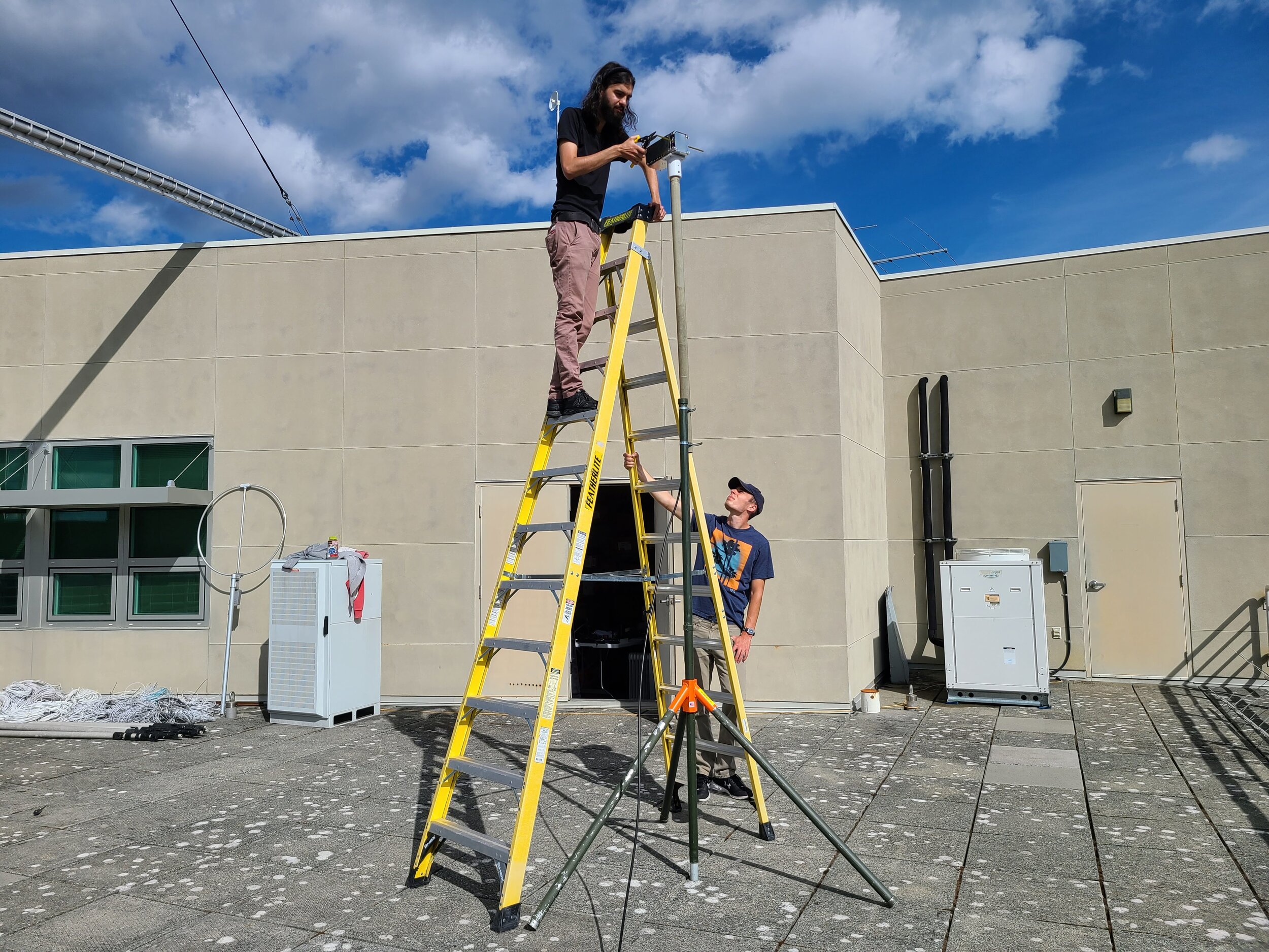

In the photos, you may have noticed TinSat (it’s not made of tin, so HackSat might be a better name), a test article which consists of the ORCASat structure with crudely made sheet metal panels attached to it. These sheet metal panels have similar electrical characteristics of the solar panels, which are not yet manufactured. It might not look pretty, but from an RF point of view it closely resembles what the flight spacecraft will look like and allows us to test without needing the solar panels.
After ground plane related problems with the first prototype, a simple feed system consisting of a W2DU style choke balun wound from RG-178 coax on Type #61 material was conceptualized. The design was split into two printed circuit boards, too - the antenna got its own board instead of being co-located with the transceiver.

The initial results look very promising. Trimming the antenna arms to shorten them shifts the resonant frequency of the antenna up. The default length arms had a resonance of around 300 MHz, and we were able to trim them down until the antenna resonance reached 435 MHz. Further testing is needed to ensure the antenna meets the rest of its requirements, but so far everything looks good!