Antenna Testing in an Anechoic Chamber
Author: Levente Buzas
As part of the verification test campaign for the dipole antenna for ORCASat, it is important to measure the absolute gain and gain pattern of this antenna. Knowing these gives more confidence in correct antenna performance and the link budget, as the presence of the spacecraft body may create detrimental deviations from the ideal pattern and gain of a dipole antenna in free space.
One common way to measure these parameters is the use of a so-called anechoic chamber. This is a facility which consists of a RF shielded room with absorbers, so no outside interference impacts the measurements undertaken within, and the internal reflections are also minimized. This is illustrated below.

At the University of Victoria, an anechoic chamber is operated by Prof. Jens Bornemanns research group, who kindly allowed the TT&C team to use it for antenna measurements. This chamber, however, is best suited for measurements at microwave frequencies above 1 GHz, so only a coarse estimate of the gain pattern and absolute gain could be attempted.
To undertake the measurements, the antenna PCB was mounted inside a satellite mock-up consisting of the aluminum flight structure covered by tin panels. This was to simulate the electromagnetic behaviour of the spacecraft body in the absence of solar panel PCBs available for testing. For mechanical support, a 3D printed pipe adapter was manufactured, allowing measurements to be undertaken in the E and H plane of the dipole. This is shown below.
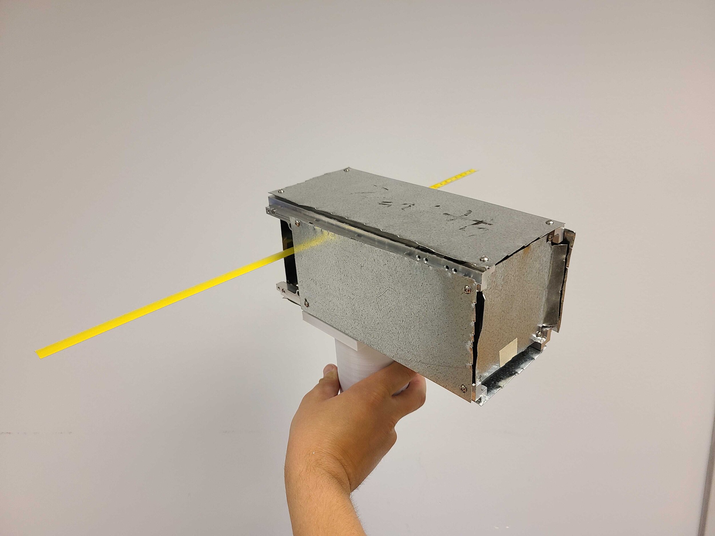
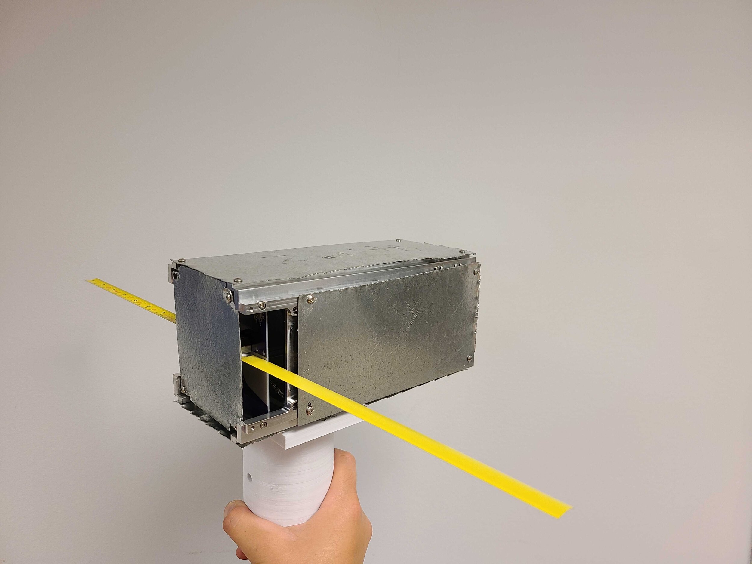
As a test antenna, a log periodic antenna was used. The test antenna and the spacecraft mock-up with the dipole were arranged such that the two devices were in each other far fields, and their supports were covered with absorbers to minimize their impact on the measurement results. This is illustrated below.

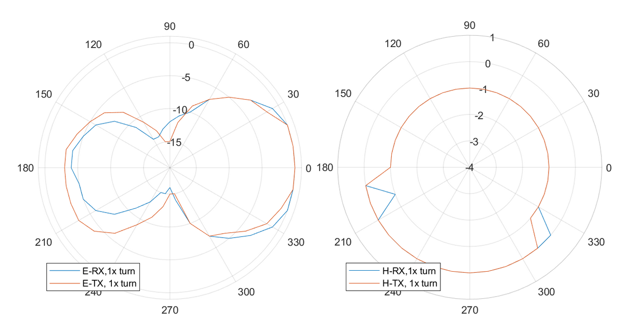
For the gain pattern, measurements were undertaken in the E and H plane, using the dipole antenna in the spacecraft mock-up as a transmitter, and later as a receiver. The pattern was measured in 10 degree increments, over 360 degrees. During the measurements, the test antenna remained stationary, and the spacecraft mock-up was rotated.
The results of the gain pattern test are shown below on normalized E-plane (left) and H-plane (right) graphs. As shown, the pattern between TX and RX is nearly identical, as expected, and the radiation pattern shape expected for a dipole (figure eight in E, circle in H plane) is also observed. It is also shown that due to the presence of the spacecraft body, the antenna has a preferential direction in the E-plane, towards the ram face of the spacecraft (0 degree, +x). This is a deviation from the ideal behaviour.
To determine the absolute gain, a different measurement was needed. The gain was measured for transmitting and receiving with the dipole antenna, in its direction of maximum radiation in the E-plane. It was determined that this gain was 0.7 dBi +2.6/-3.1 dB, which is a reasonable result, given that a dipole in theory has a gain of ~ 2dBi and that the chamber was not suited for the frequency range this measurement was taken in.
Overall, the measurements in the anechoic chamber did not produce any surprises. It was determined that the antenna indeed behaves as a dipole, and it offers a gain which is not unreasonable. This further increases the team’s confidence in this critical block of the TT&C subsystem, and decreases uncertainties associated with the link budget. With these critical tests completed, the next step in the antenna test campaign is the final verification of the dipole by a 3D pattern scan - this will be undertaken by a commercial antenna testing facility to gain complete confidence in the performance of the antenna.